During the last year, a working group has developed an extension for DEXPI to cover block flow diagrams (BFD) and process flow diagrams (PFD). The existing DEXPI specification defines an information model for Piping and Instrumentation diagrams (P&ID). This covers the equipment and piping aspects of engineering and construction of a process plant. However, there is no corresponding information model applicable for PFDs and BFDs. This is a gap in the coverage of standards in process engineering. The PFD and BFD document the process and functional aspects of the design that are developed in early-phase engineering and provide the design constraints for detailed design, procurement and construction.
The model developed represents the information in PFDs and BFDs. In addition, it provides a data model for representing process design in a way that allows traceability of requirements and design choices through the engineering lifecycle. The model describes the process systems that are represented in the diagrams. It also provides a framework for defining and providing the design data that is shown on PFDs.
The DEXPI+ model forms as additional package, called Process, in the DEXPI information model.
A presentation layer (to be developed) will allow this information model to be rendered as a PFD or BFD. Together, the model and the presentation layer provide a standard exchange format for these diagrams.
The information model represents the process in a facility, as distinct from the plant, which is the realization of these processes by means of the specification of Apparatuses, Machines, Pipelines etc. We model the process as a set of interconnected process steps, where a process step is a system that performs a process activity. A process step can represent a block in a BFD or an item in PFD. Note that this means that a symbol in a PFD has a different meaning to a symbol in a P&ID. A distillation column symbol in a P&ID represents a piece of equipment (also called Plant Item or TAG by the engineers), whereas the same symbol in a PFD represents a process step: a distillation system.
A process step is connected to other process steps using ports. A port is the location for an inflow or outflow of material, energy or information. Ports are connected by process connections, which are material flows (streams), energy flows (thermal, electrical or mechanical) or information flows.
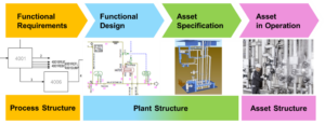
This approach is consistent with the OntoCAPE ontology and is aligned with system breakdown standards such as ISO/IEC 81346 and DIN 6779-13. It covers the functional requirements and process structure aspects in the ENPRO lifecycle model.
Process activities in DEXPI+ are characterized by a verb. In naming our classes we use the imperative form (e.g. Compress, Extrude) unless this is ambiguous (e.g. Pump) or inelegant. In these cases we use the present participle form (e.g. Pumping, Regulating). Names of unit operations are formed by adding the noun for the object of the action (e.g. RegulatingFlow) or an adverbial phrase about how the activity is done (e.g. SeparateByCentrifugalMotion). Reference data for these activities is only partly available in ISO 15926. We need to implement these types in RDL.
The data model is currently published as a UML model and an XML schema. It defines a library of process step blocks that cover a wide range of chemical processes. Each process step contains parameters that can be specified or calculated during process design.
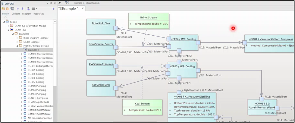
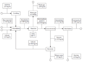
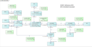
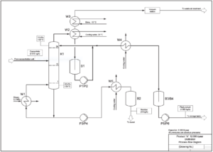
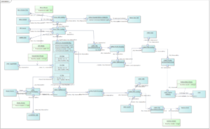
The DEXPI+ standard was demonstrated by modelling BFDs and PFDs from the ISO 10628 standard. The following diagrams show the original diagram and the DEXPI+ model drawn as a UML class diagram, for both a BFD and a PFD.
The DEXPI+ standard is available for comment. We believe that it provides a good starting point for a standard, graph-based representation of chemical processes. Work is planned in 2023 to define a presentation format for the model. We also believe that there is potential to use this model as a framework for extracting data from process simulators in the design process.